Frohe Weihnachten 2024
25 December, 2024
Painting made by @jamila.draws on Instagram

25 December, 2024
Painting made by @jamila.draws on Instagram

21 December, 2024
Taken at the 2024 Winter Solstice ♑︎, the shortest day of the year.
This panorama is the 2024 Winter Solstice contribution for the 'December Wrinkle' event of WorldWidePanorama.
Interactive Panorama Overlake Hospital
I took this panorama about an hour before sunset without a tripod while waiting at the main exit. The main challenge was aligning the pathway with the building's geometric facade.
Taking more pictures than necessary helps with panoramas because it allows for better adjustments and alignment.
Using the mask feature in PTGui is another significant advantage. It allows you to force the seamlines into less prominent areas, thereby minimizing visible overlaps and reducing poor alignment.
1/60s f/5,6 ISO 100/21° 7,5mm
Only the central parts of the images were used, which minimized errors. Note the nearly uniform size of the horizontal image parts, with the exception of the pair on the left side of the large building.
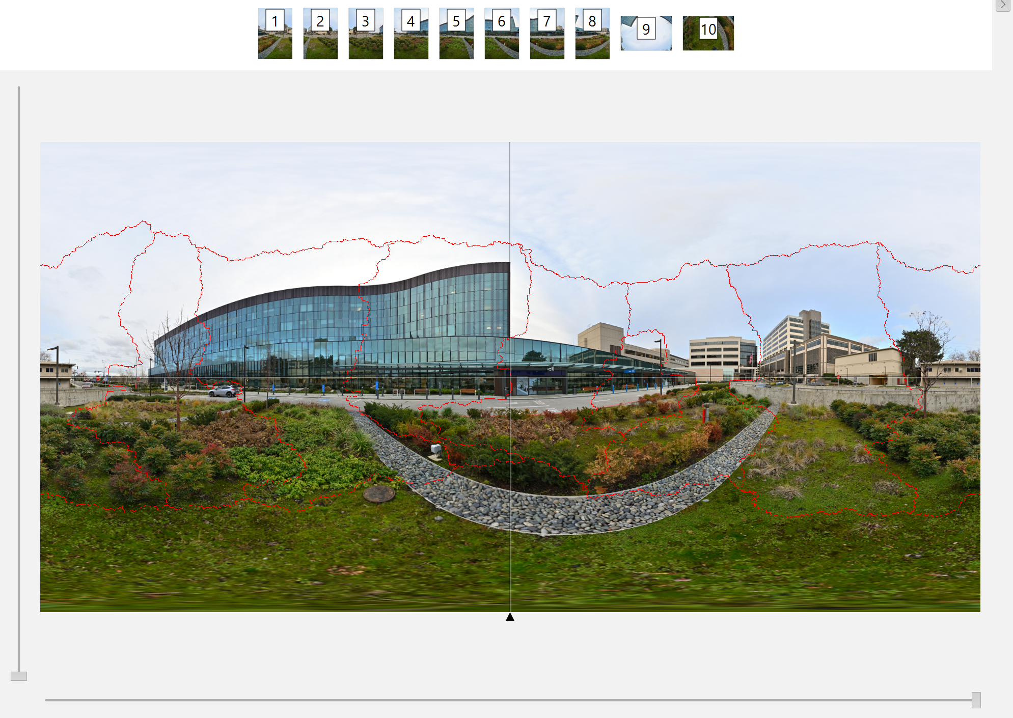
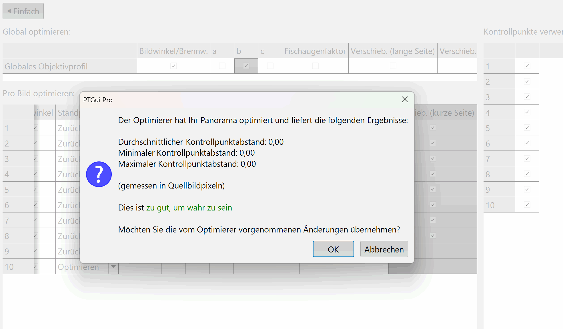
At one point, I had this rare PTGui result:
30 November, 2024
The C++ standard does not allow the usage of a function inside another function. Instead, a lambda expression can be used to achieve this functionality.
For instance, it is not permissible to define this function within another function. However, you can achieve the same functionality by using a lambda expression as follows:
// function definition
BYTE grey_sum(int x, int y)
{
    const int index(3 * ((rect_y + y) * requested_data2.picture_width + rect_x + x));
    const BYTE grey(data[index]);
    return grey;
}
The lambda syntax starts with the capture clause [=] to have read access on all the variables in the scope (use an empty clause [] to access only local variables, or use [&] to use all the variables as references, or list explicitly which variables are used by value and which by reference, for example: [a, &b]), the argument list (int x, int y) and then the return type -> BYTE. The mutable specification and the exception specification are optional and not used here.
The lambda is then used like a function: grey_sum1 += grey_sum(x1, y1);
// equivalent lambda definition
auto grey_sum = [=](int x, int y) -> BYTE
    {
        const int index(3 * ((rect_y + y) * requested_data2.picture_width + rect_x + x));
        const BYTE grey(data[index]);
        return grey;
    };
See this example from the AsciiArt plugin for cPicture (github link).
Using a traditional function would necessitate passing all local data as arguments, which can be inefficient. In contrast, a lambda expression provides a more streamlined and effective approach by capturing local variables directly within its scope.
    // Lambda to calculate the grey value.
    auto grey_sum = [=](int x, int y) -> BYTE
        {
            const int index(3 * ((rect_y + y) * requested_data2.picture_width + rect_x + x));
            const BYTE grey(data[index]);
            return grey;
        };

    // Read the rect segment at (rect_x, rect_y).
    for (register int y1 = 0; y1 < rect_h / 2; y1++)
    {
        for (register int x1 = 0; x1 < rect_w / 2; x1++)
            grey_sum1 += grey_sum(x1, y1);

        for (register int x2 = rect_w / 2; x2 < rect_w; x2++)
            grey_sum2 += grey_sum(x2, y1);
    }
    for (register int y2 = rect_h / 2; y2 < rect_h; y2++)
    {
        for (register int x1 = 0; x1 < rect_w / 2; x1++)
            grey_sum3 += grey_sum(x1, y2);

        for (register int x2 = rect_w / 2; x2 < rect_w; x2++)
            grey_sum4 += grey_sum(x2, y2);
    }

    const int rect_area4 = rect_area / 4;

    // Lambda to check if the contrast and brightness adjusted grey sum exceeds the threshold.
    auto match = [=](__int64 grey_sum) -> bool
        {
            return ((grey_sum / rect_area4 - 127) * (100 - contrast) / 100 + brightness + 127) <= 127;
        };

    // rect area is divided into 4 equal parts
    // 12
    // 34
    const bool b1 = match(grey_sum1);
    const bool b2 = match(grey_sum2);
    const bool b3 = match(grey_sum3);
    const bool b4 = match(grey_sum4);
13 October, 2024
For the EV diff plugin in cPicture, which calculates the exposure difference between pictures, I needed a simple aggregate to print the parameters used.
For example, the list values 1, 2 and 3 should be converted to the string "(1, 2, 3)". An aggregate function maps an enumerable type (vector) to a plain type (string). The function takes the vector, the toString lambda to convert individual vector elements to a string, and the start/end text and the separator.
I wanted to create a function similar to the Join-String function in PowerShell that is both simple and versatile. This is my implementation:
template<class T>
CString JoinString(typename vector<T>::const_iterator begin,
    typename vector<T>::const_iterator end,
    const function<CString(typename T)>& toString,
    const CString& startText,
    const CString& endText,
    const CString& separator)
{
    CString text(startText);

    for (typename vector<T>::const_iterator it = begin; it != end; ++it)
    {
        // Use the lambda to convert the template type data to text.
        text += toString(*it);

        // Skip separator for last element.
        if (it != end - 1)
        {
            text += separator;
        }
    }

    return text + endText;
}
Test case for JoinString using int data.
The input is a vector of three ints which gets converted to a string that starts with an opening bracket '(', separates the elements with a comma ',' and ends with a closing bracket ')'. The toString lambda 'getText' converts the data to a string.
vector <unsigned int> matchList = { 1, 2, 3 };

// toString lambda expression
auto getText([](auto id) { CString text; text.Format(L"%d", id); return text; });

const CString matchParameter(JoinString<unsigned int>(matchList.begin(), matchList.end(), getText, L"(", L")", L", "));

Assert::AreEqual(L"(1, 2, 3)", matchParameter);
Test case for JoinString using string data.
The lambda simply passes the data and can be inlined.
vector <CString> strList = { L"a", L"b", L"c" };

const CString combinedText(JoinString<CString>(strList.begin(), strList.end(), [](auto text) { return text; }, L"[", L"]", L"+"));

Assert::AreEqual(L"[a+b+c]", combinedText);
05 October, 2024
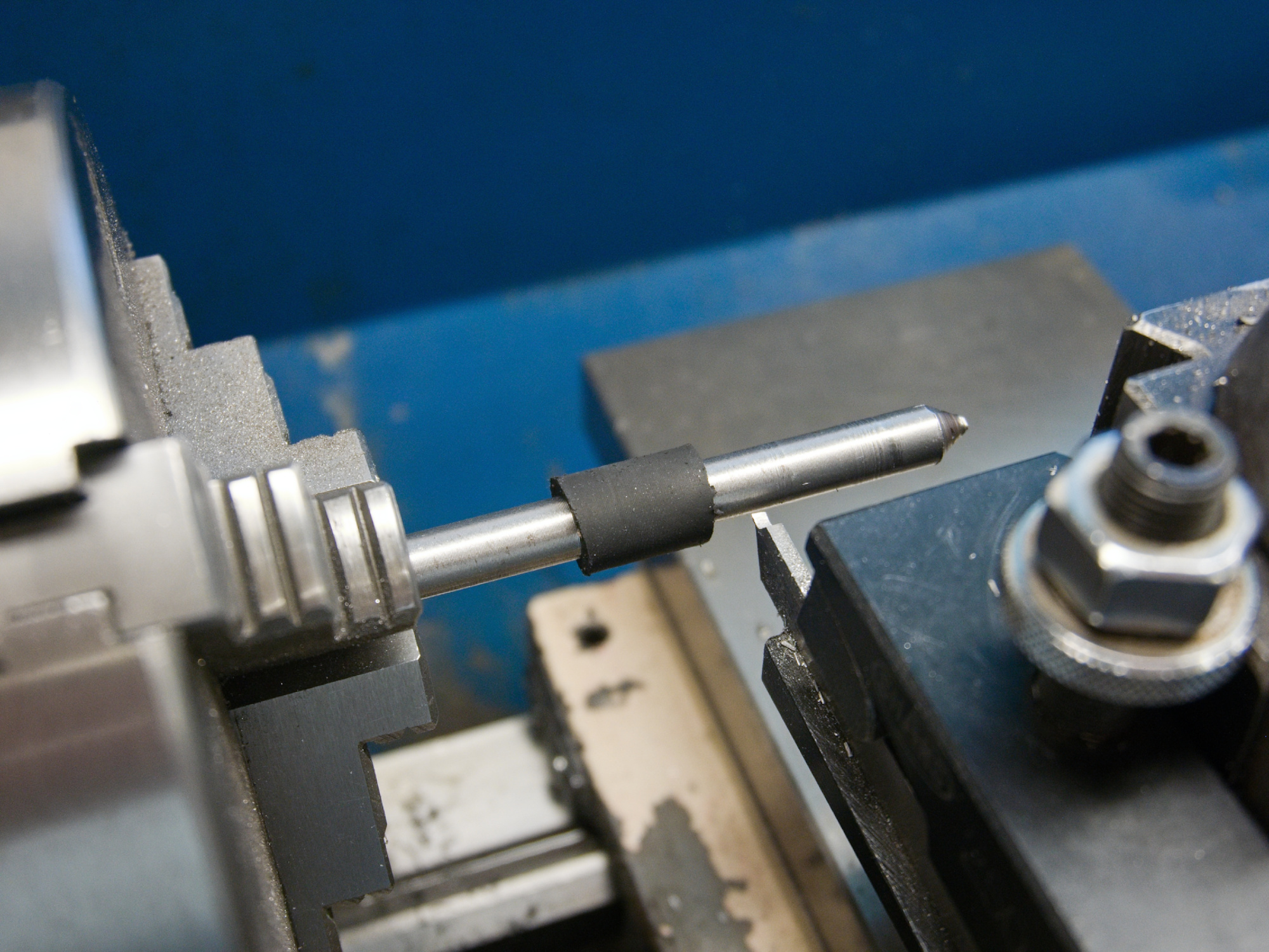
To prevent any oil leak via the clutch shaft passing, add a piece of rubber tube over the clutch shaft and adjust the diameter for a perfect fit inside the input gear shaft.
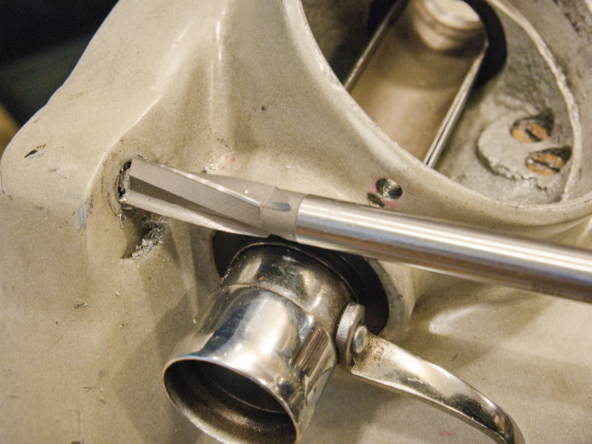
The mounting flange on the gearbox is slanted. Use a counterbore drill to make the mounting flange perpendicular.
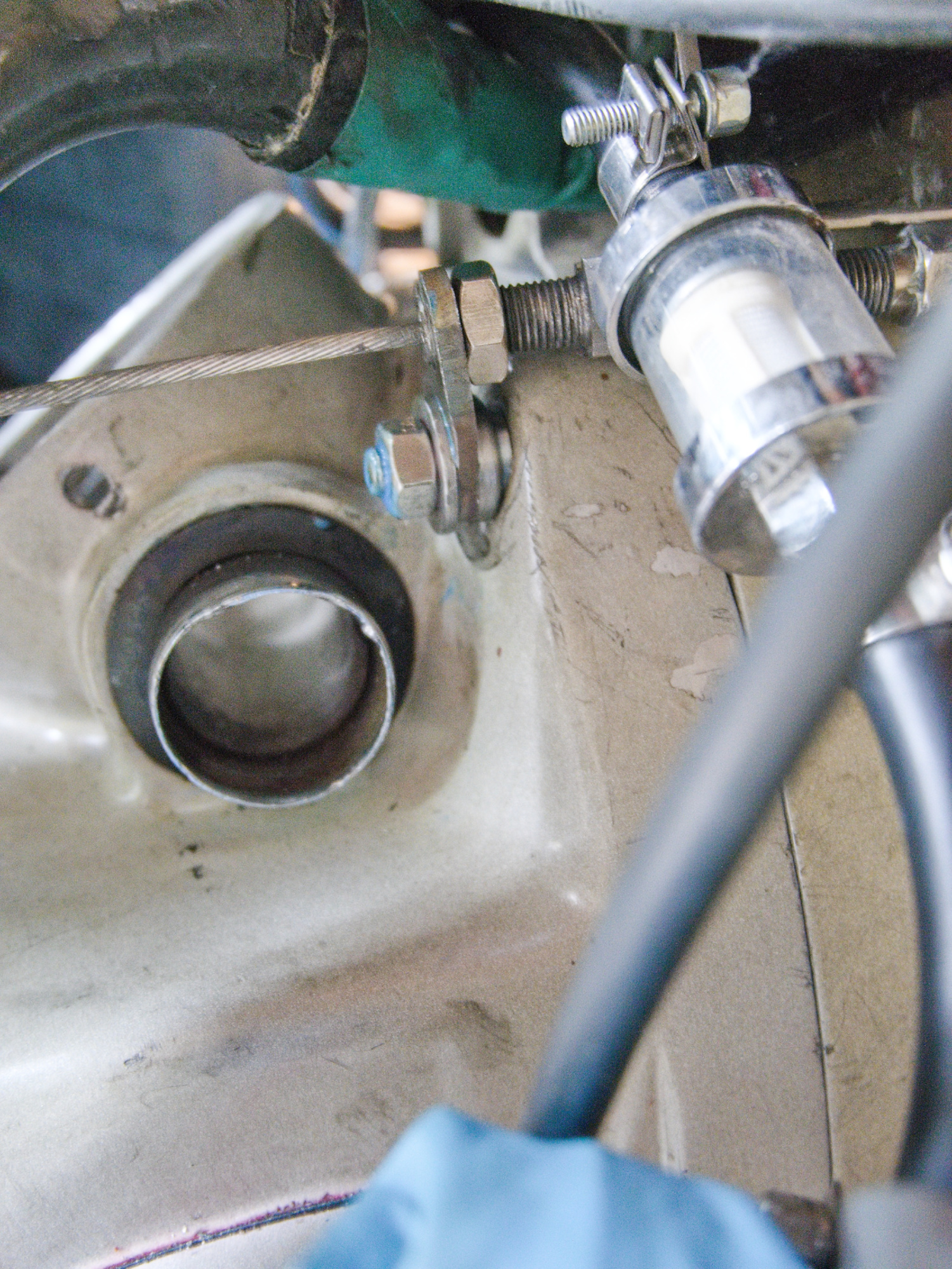
This is my clutch cable holder that gets mounted on the gearbox. Using the small machined tube part, it takes out any play that would otherwise cause the normal holder to flex and bend the stud each time the clutch is activated.
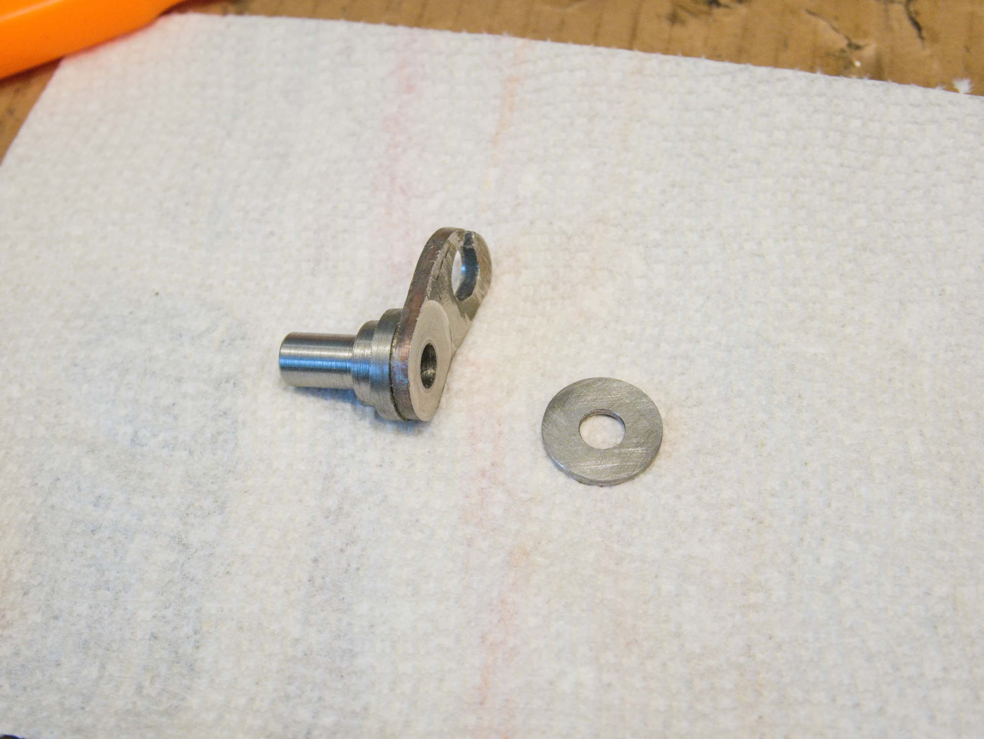
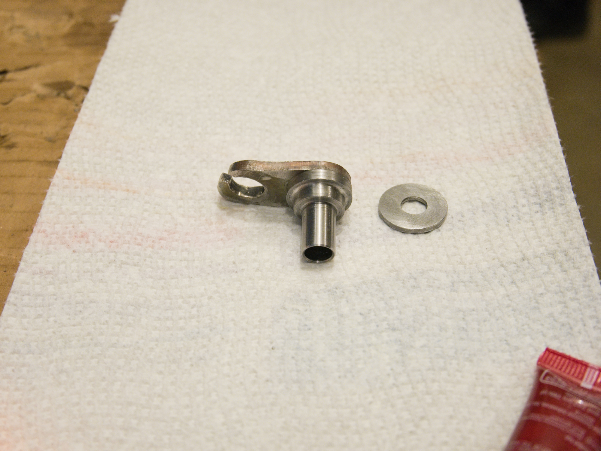
The new clutch cable holder is now precisely mounted.
05 October, 2024
Use Loctite 518 gasket maker for the reverse shifter plate.
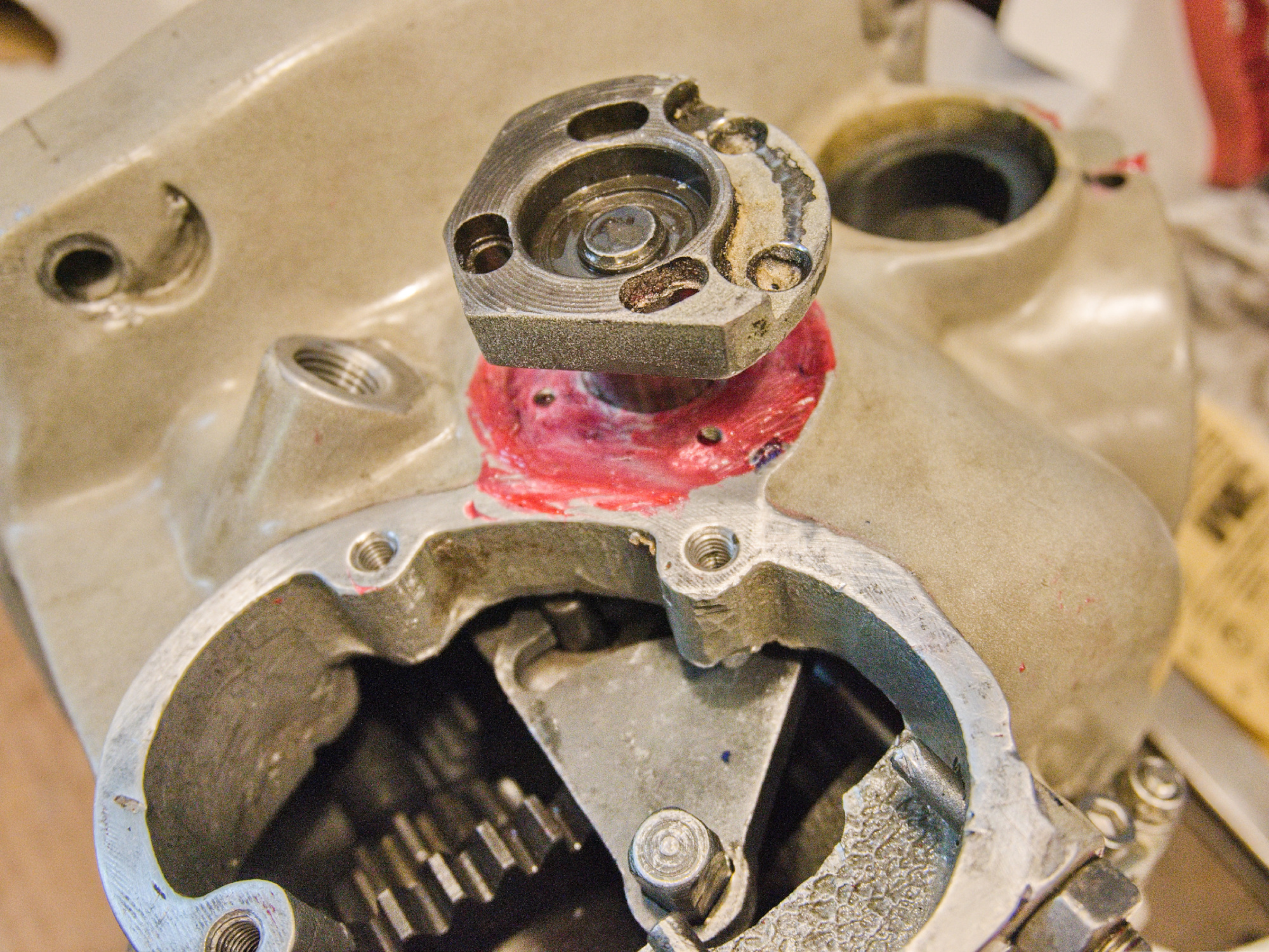

Add the gaskets.
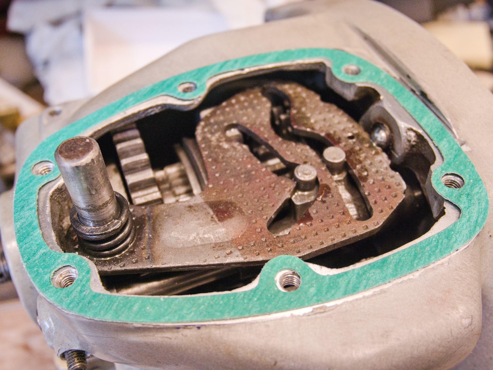
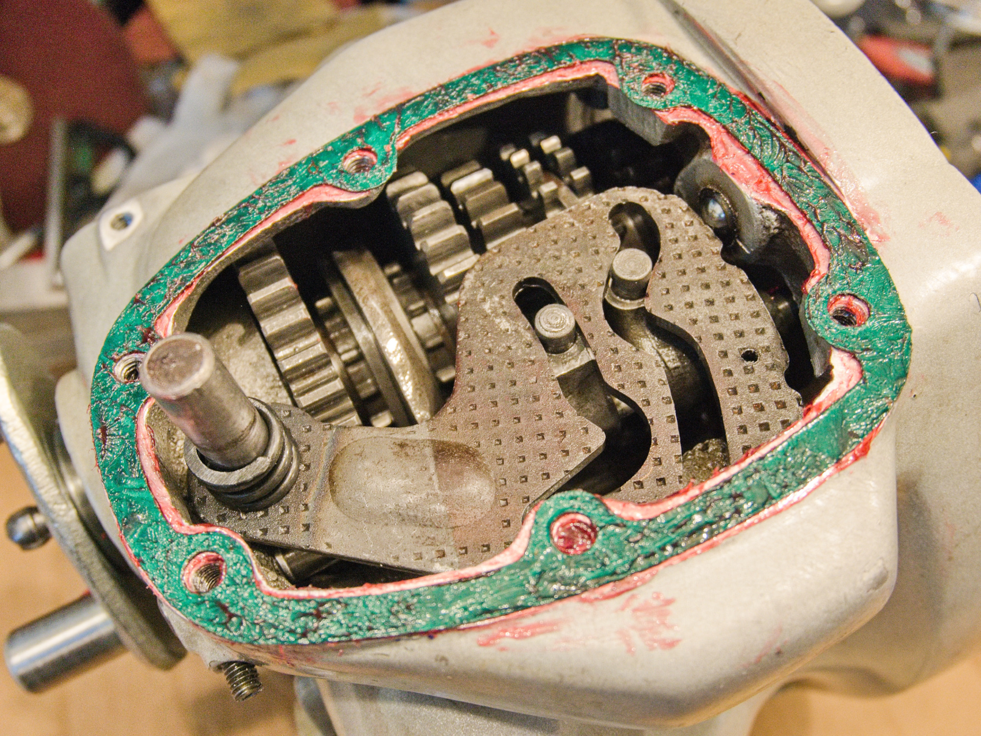
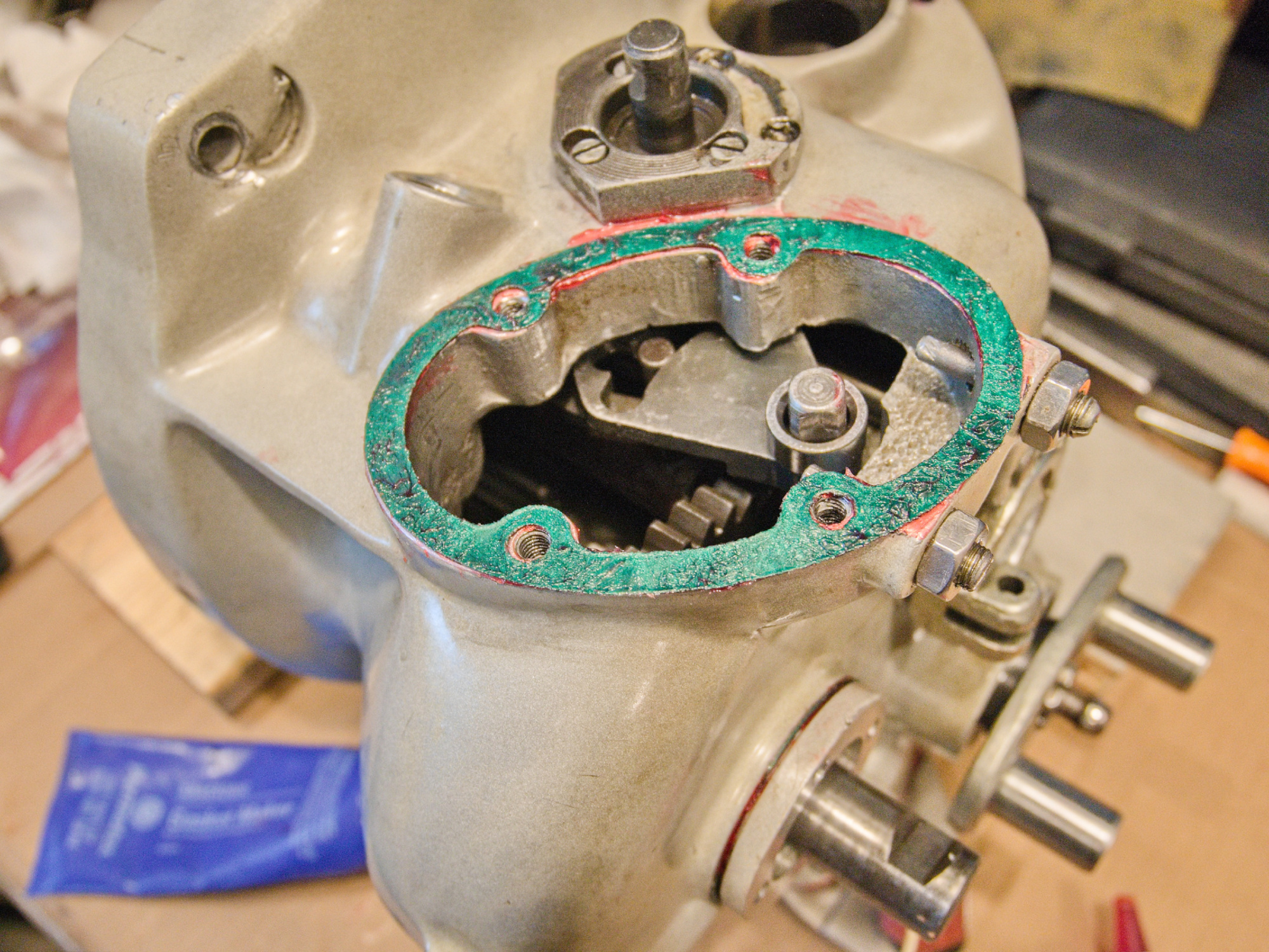
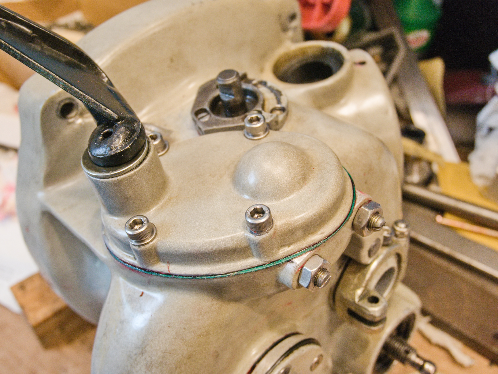
I created a simple tool to turn the kick start spring front cover.
But a large plier would also work.
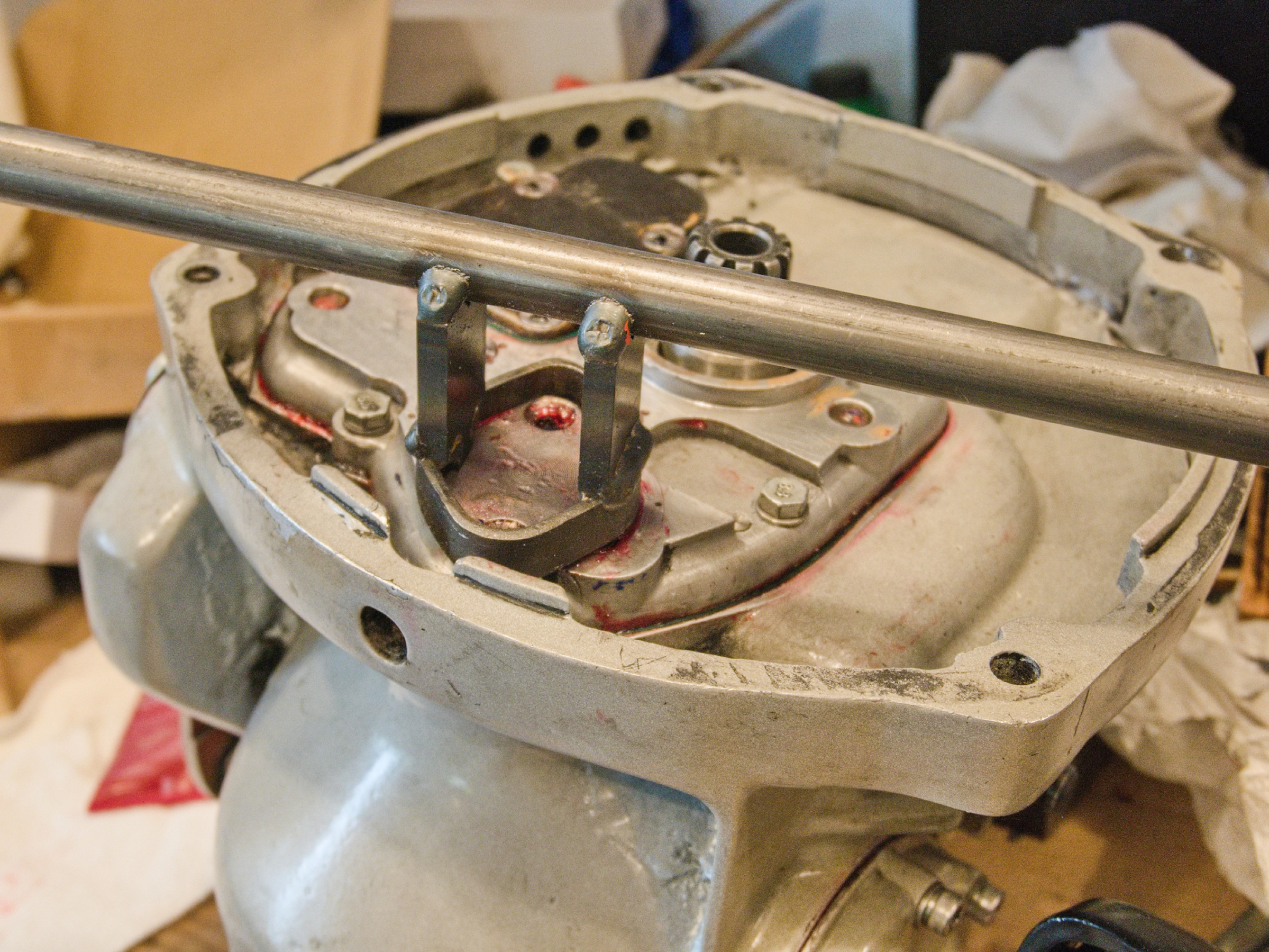
Add gasket maker to the screw holes for a oil tight seal. This also works like a thread locker. No need to punch in the small holes to lock the screw as it was done before. Those three large screws only hold the reverse gear shaft and do not need much torque anyway.
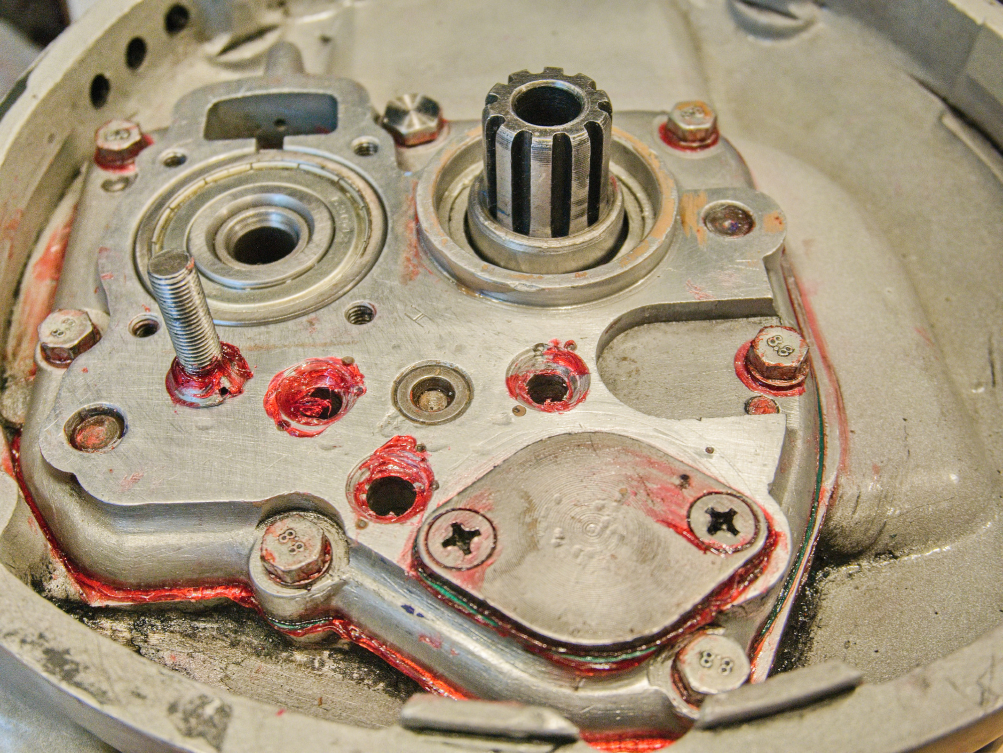
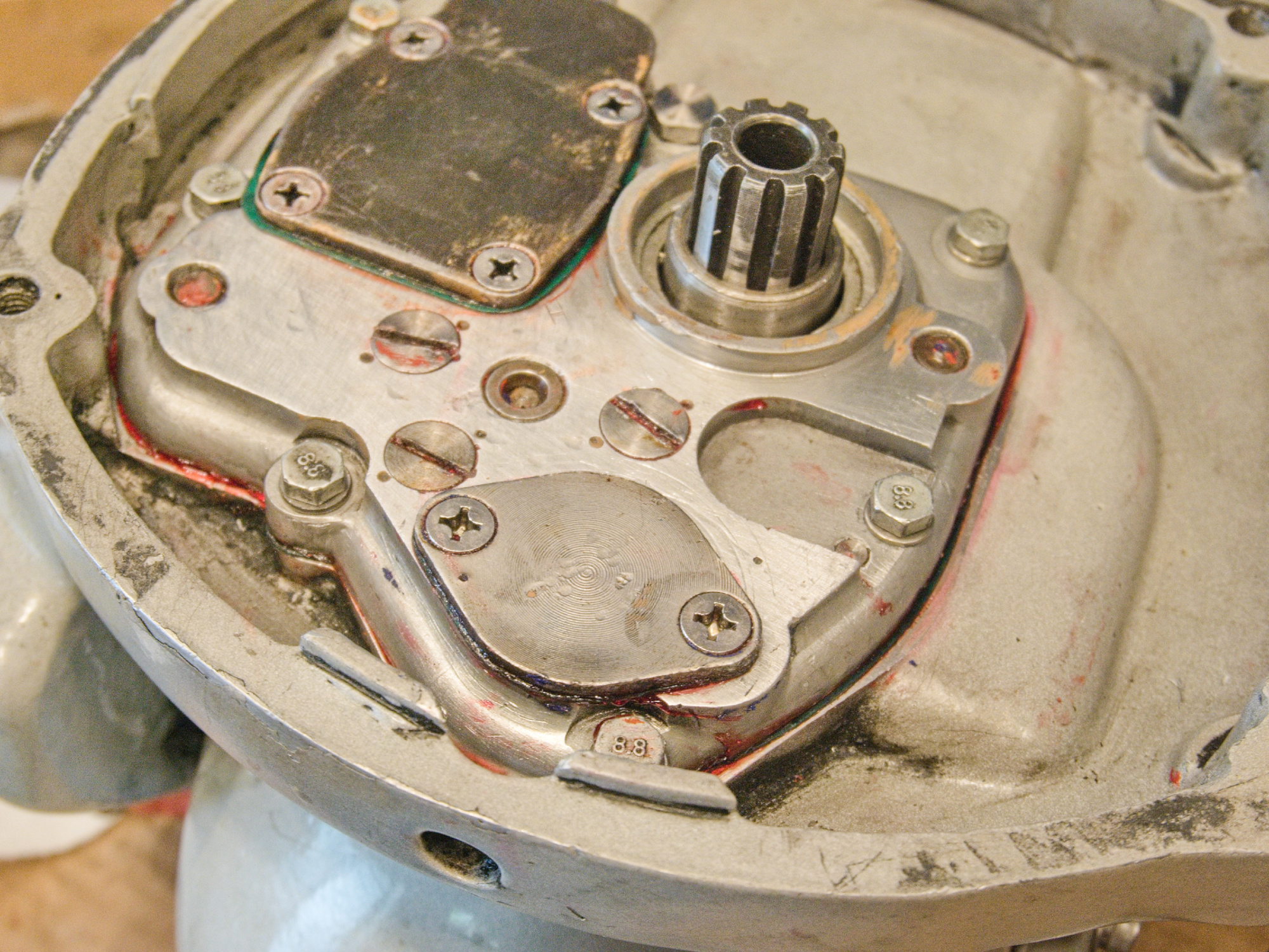
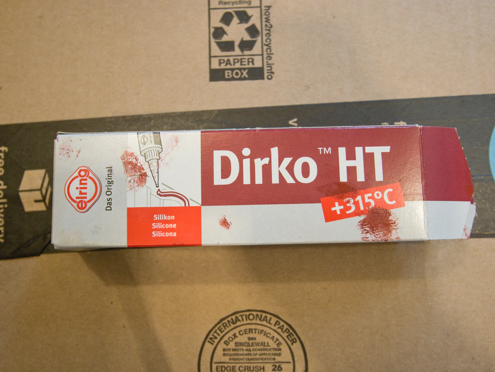
Add Dirko (very sticky silicone sealer) to the end of the transmission rods. It will leak from there over time, even it is only a very small amount of oil.
Make sure the distance ring for the bearing that is hold with the (black) output shaft cover plate provide enough play.
Add the test adapter, and make a test run to make sure everything is running smoothly.
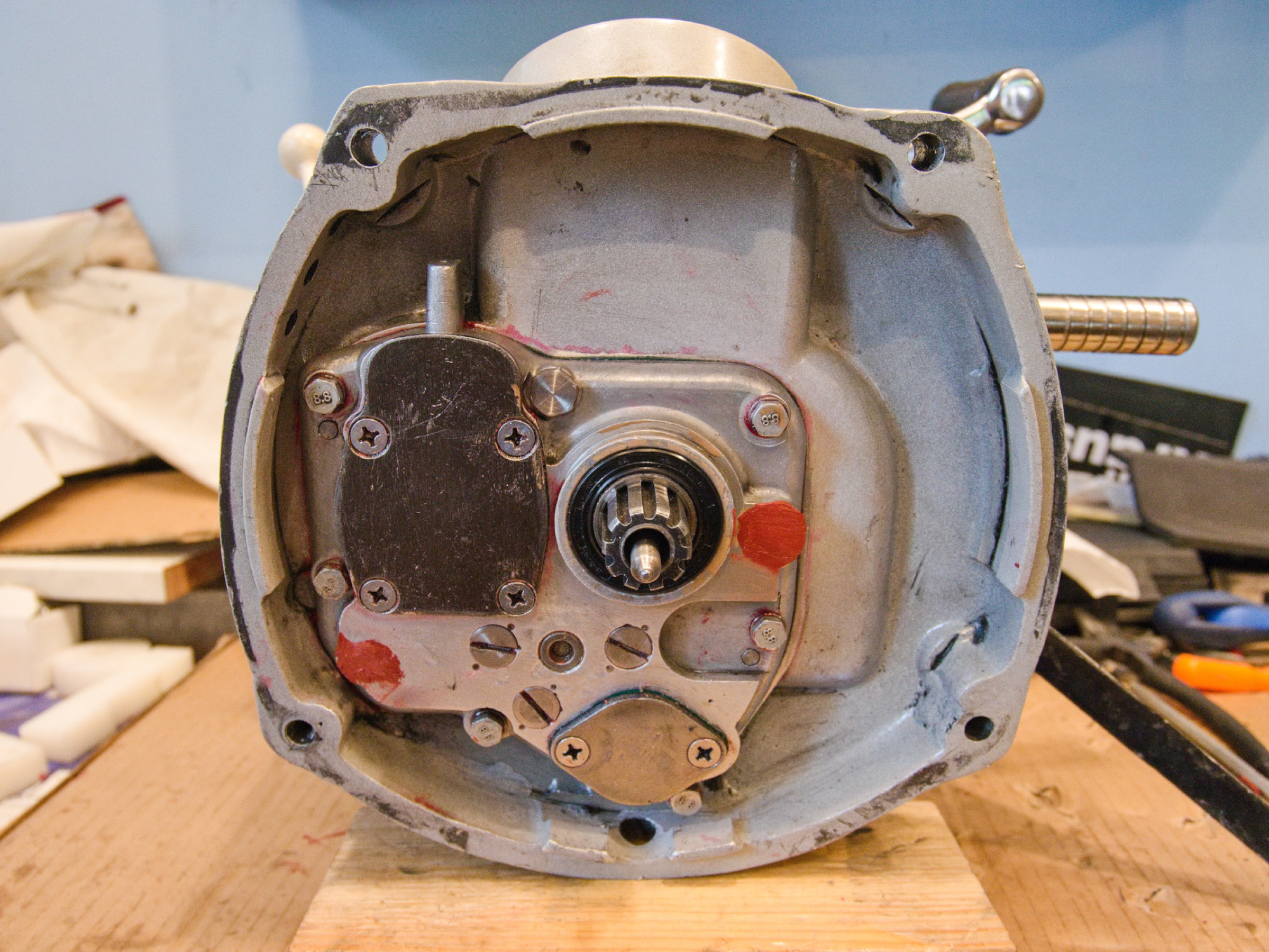
Along with the rebuild final drive, it makes for a perfect drive train.
1st and 2nd gears remain powerful with the 8/37 final drive, but 3rd and 4th now feel like they’re using a high-speed final drive, which is ideal. Previously, I had a high-speed final drive, but starting in 1st gear with a sidecar was challenging, especially on uphill climbs.